Accessories: Solar Thermal Energy
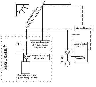
General scheme of solar energy accessories
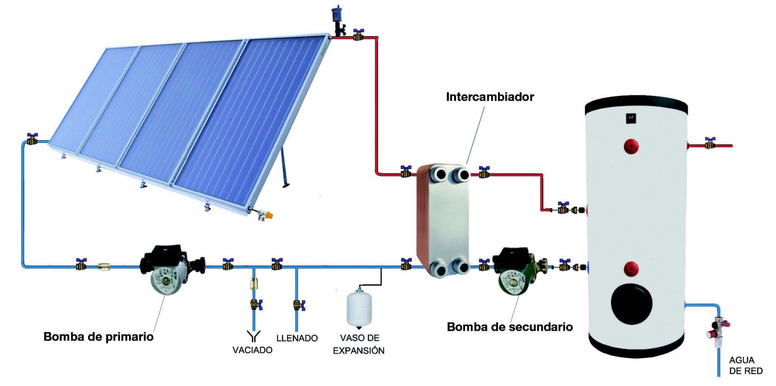
Heat transfer kits
| Power (Kw) | Description | Reference |
|---|---|---|
| 35 | Kit with cover box | 702KIACSTIA |
Brazed-plate heat exchangers for DHW
Design conditions
– Primary circuit liquid temperature = 60ºC
– Secondary circuit liquid outlet temperature = 50ºC
– Primary circuit working liquid = propylenglicol 30 %
– Secondary circuit working liquid = water
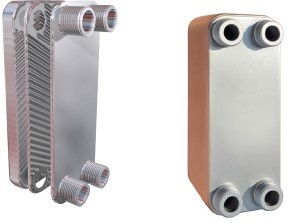
| Collectors area (m2) | Power | Inlets | Reference | P.V. P € |
|---|---|---|---|---|
| 28,8 | 6 – 15 kW | 3/4” | 702PTACS012 | – |
| 48 | 16 – 24 kW | 3/4” | 702PTACS020 | – |
| 84 | 25 – 42 kW | 1” | 702PTACS035 | – |
| 120 | 43 – 60 kW | 1” | 702PTACS050 | – |
| 144 | 61 – 72 kW | 1” | 702PTACS060 | – |
| 168 | 73 – 84 kW | 1” | 702PTACS070 | – |
| 216 | 85 – 108 kW | 1” | 702PTACS090 | – |
| 240 | 109 – 120 kW | 1 1/4” | 702PTACS100 | – |
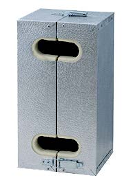
Insulations
| Insulations up to | Reference | P.V. P € |
|---|---|---|
| 48 m2 collectors | 702PTAIS020 | – |
| 84 m2 collectors | 702PTAIS035 | – |
| 144 m2 collectors | 702PTAIS060 | – |
| 216 m2 collectors | 702PTAIS090 | – |
| 240 m2 collectors | 702PTAIS120 | – |
Shell-and-tube heat exchangers for swimming pool heating
- Solar installation power conditions: Input primary circuit T = 50ºC
- Boiler installation power conditions: Input primary circuit T = 90ºC
- Maximum flow in tube 15 m3/h
25 kW
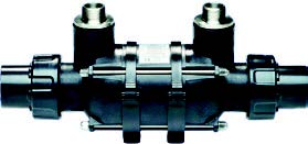
45 kW
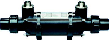
85 kW

105 kW

Int. Stainless steel heat exchangers for non saline water pools
| Collectors area (m2) | Solar installation power / Boiler installation power | Reference |
|---|---|---|
| 2- 12 | 1 – 6 kW / 25 kW | 702CT025I05 |
| 12 – 35 | 7 – 18 kW / 45 kW | 702CT045I15 |
| 35 – 71 | 19 – 36 kW / 85 kW | 702CT085I30 |
| 71 – 82 | 37 – 42 kW / 105 kW | 702CT105I35 |
Int. Titanium heat exchangers for saline water pools
| Collectors area (m2) | Solar installation power / Boiler installation power | Reference |
|---|---|---|
| 2 – 12 | 1 – 6 kW / 25 kW | 702CT025T05 |
| 12 – 35 | 7 – 18 kW / 45 kW | 702CT045T15 |
| 35 – 71 | 19 – 36 kW / 85 kW | 702CT085T30 |
| 71 – 82 | 37 – 42 kW / 105 kW | 702CT105T35 |
PUMPING UNITS
1 way without controller
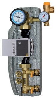
- Circulating pump
- 1 Flow regulator (2 – 12 l/min || 8 – 38 l/min)
- 1 Thermometer (impulsion)
- 1 Safety valve (6 bar)
- 1 Pressure gauge
- 1 Filling valve and 1 emptying valve
- 1 Pressure gauge
- Thermal insulation
| Description | Net area m2 | HMAX (m. c. a) | Pump | Inlets | Reference |
|---|---|---|---|---|---|
| Pumping unit 1W – without controller | < 25 m2 | 6,8 | Wilo ST 25/6 iPWM | ¾ ” M | 704B12L1V070 |
| Pumping unit 1W – without controller | < 50 m2 | 8,5 | Wilo ST 25/8 iPWM | 1” M | 704B38L1V075 |
1 way with controller

- Circulating pump
- 1 Flow regulator (2 – 12 l/min || 8 – 38 l/min)
- 1 Thermometer (impulsion)
- 1 Safety valve (6 bar)
- 1 Non-return valve
- 1 Pressure gauge
- 1 Filling valve and 1 emptying valve
- 1 Pressure gauge
- Thermal insulation
- Controller STDC
| Description | Net area m2 | HMAX (m. c. a) | Pump | Inlets | Reference |
|---|---|---|---|---|---|
| Pumping unit 1W – with controller STDC | < 25 m2 | 6,8 | Wilo ST 25/6 iPWM | ¾ ” M | 704B12L1V170 |
| Pumping unit 1W – with controller STDC | < 50 m2 | 8,5 | Wilo ST 25/8 iPWM | 1” M | 704B38L1V175 |
2 ways with controller
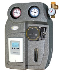
- Circulating pump
- 1 Flow regulator (2 – 12 l/min || 8 – 38 l/min)
- 2 Thermometers (impulsion and return)
- 1 Safety valve (6 bar)
- 1 Non-return valve
- 1 Pressure gauge
- 1 Filling valve and 1 emptying valve
- 1 Pressure gauge
- Thermal insulation
- Controller MTDC
| Description | Net area m2 | HMAX (m. c. a) | Pump | Inlets | Reference |
|---|---|---|---|---|---|
| Solar station 2W – with controller MTDC | < 25 m2 | 6,8 | Wilo ST 25/6 iPWM | ¾ ” M | 704B12L2V170 |
| Solar station 2W – without controller | < 50 m2 | 8,5 | Wilo ST 25/8 iPWM | 1” M | 704B38L2V075 |
| Solar station 2W – with controller MTDC | < 50 m2 | 8,5 | Wilo ST 25/8 iPWM | 1” M | 704B38L2V175 |
2 ways drainback
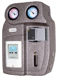
- Circulating pump
- 1 Flow regulator (2 – 12 l/min || 8 – 38 l/min)
- 2 Thermometers (impulsion and return)
- 1 Safety valve (6 bar)
- Without Non-return value
- 1 Filling valve and 1 emptying valve
- Thermal insulation
- Controller MTDC
| Description | Net area m2 | HMAX (m. c. a) | Pump | Inlets | Reference |
|---|---|---|---|---|---|
| Solar station 2W – with controller MTDC | < 25 m2 | 6,8 | Wilo ST 25/7,5 iPWM | 1″ M | 704D12L2V175 |
| Solar station 2W – with controller MTDC | < 25 m2 | 6,8 | Wilo Para ST 15/13 iPWM | 1” M | 704D12L2V113 |
Dynamic heat sinks
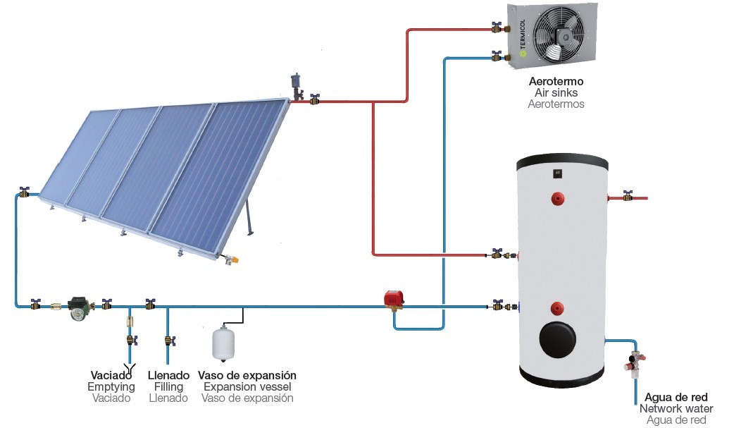
Models
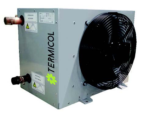
Heat sinks
| Nº Collector | Collectors Models | Description | Reference |
|---|---|---|---|
| 1 – 4 1 – 5 |
S26, G26, S21, G21, P21 |
8 kW | 705DI008M |
| 5 – 9 6 – 12 |
S26, G26, S21, G21, P21 |
18 kW | 705DI018M |
| 10 – 13 13 – 16 |
S26, G26, S21, G21, P21 |
24 kW | 705DI024M |
| 14 – 21 17 – 26 |
S26, G26, S21, G21, P21 |
40 kW | 705DI040M |
| 22 – 27 27 – 34 |
S26, G26, S21, G21, P21 |
52 kW | 705DI052M |
| 28 – 32 35 – 40 |
S26, G26, S21, G21, P21 |
61 kW | 705DI061M |
| 33 – 40 41 – 50 |
S26, G26, S21, G21, P21 |
76 kW | 705DI076M |
| 41 – 50 51 – 70 |
S26, G26, S21, G21, P21 |
106 kW * | 705DI106T |
| 51 – 80 71 – 100 |
S26, G26, S21, G21, P21 |
152 kW * | 705DI152T |
| 81 – 100 101 – 125 |
S26, G26, S21, G21, P21 |
190 kW * | 705DI190T |
| 101 – 125 126 – 160 |
S26, G26, S21, G21, P21 |
243 kW * | 705DI243T |
| 126 – 155 161 – 200 |
S26, G26, S21, G21, P21 |
304 kW * | 705DI394T |
*Heat sinks of 106 kW. 152 kW and 190 kW are triple phase, the rest are single phase
Design conditions
Intake liquid temperature = 90ºC
Intake air temperature = 35ºC
Working liquid propylenglicol 30 %
***Contact technical department for models of a higher power
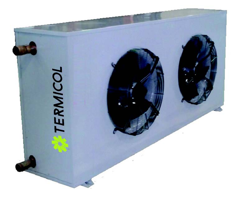
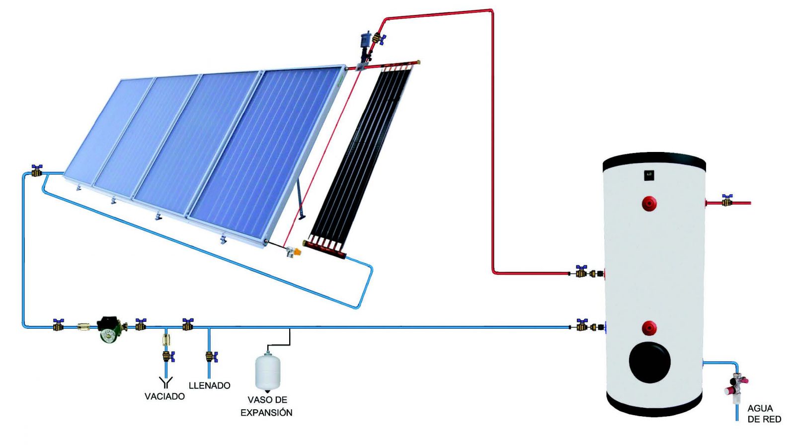
Static heat sinks
Models
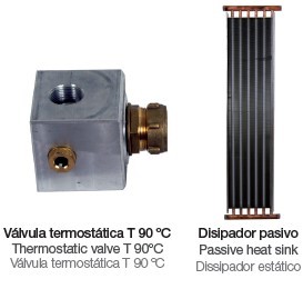
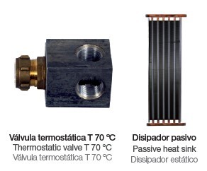
For Thermosiphon kits
| Nº Collector | Collectors Models | Description | Reference |
|---|---|---|---|
| 2 | S21,T20, T25, P21, S26 | 1.750 W | 705ECT175 |
| Descripció | Ref. |
|---|---|
| Connection for Thermosiphon kits (static heat sinks) | 211BATCAP3 |
For collector arrays
| Nº Collector | Collectors Models | Description | Reference |
|---|---|---|---|
| 2 | S21, G21, P21 | 2.500 W | 705ECF025 |
| 2
3 |
S26, G26, S21, G21, P21 |
3.500 W | 705ECF035 |
| 3
4 |
S26, G26, S21, G21, P21 |
4.500 W | 705ECF045 |
| 4
5 |
S26, G26, S21, G21, P21 |
5.500 W | 705ECF055 |
| 5
6 |
S26, G26, S21, G21, P21 |
7.000 W | 705ECF070 |
| 6 | S26, G26 | 8.000 W | 705ECF080 |
| 8 | S26, G26 | 11.000 W | 705ECF110 |
| Description | Ref. |
|---|---|
| Connection for collectors array (statics heat sinks) | 211BATCAP2 |
*Design conditions for heat sinks placed in horizontal position; wind speed 0 m/s ; Δ t =70 ºC; ramp 5%.
* Thermostatic valve included in the heatsink
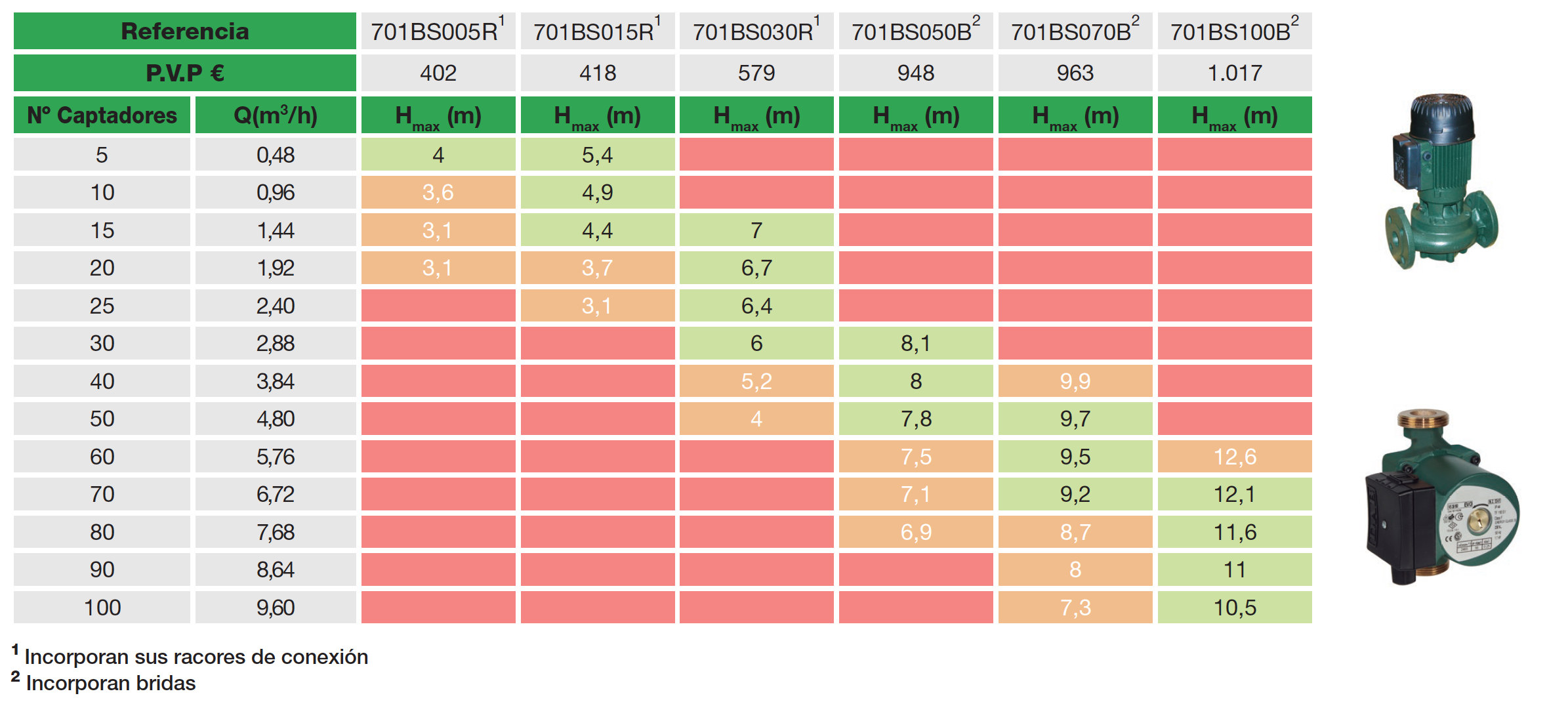
Circulation Pumps
For primary circuits: Simple Pumps
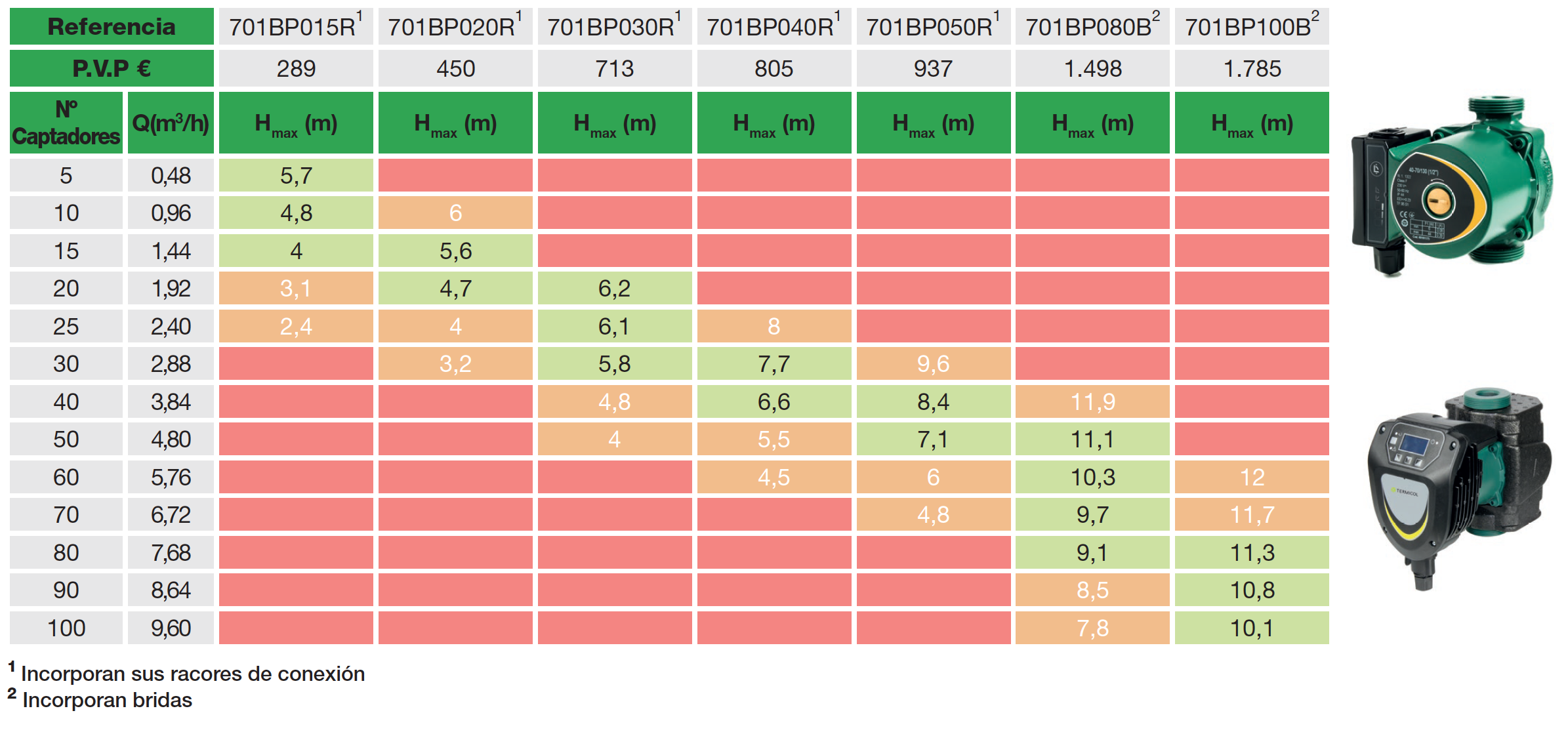
For primary circuits: Double Pumps
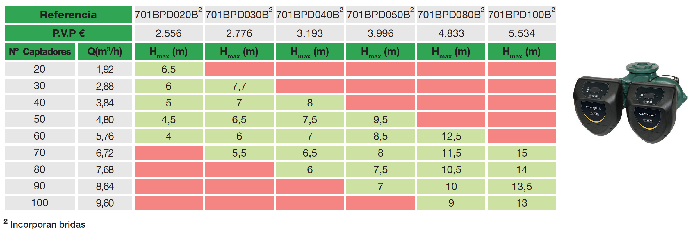
For secondary circuits: Simple Pumps
VALVES
High-flow thermostatic mixing valves
With non-returns

| Description | Referencia |
|---|---|
| Thermostatic mixing valve 1 1/4″ | 708TMZ114CAR |
| Thermostatic mixing valve 1 1/2″ | 708TMZ112CAR |
| Thermostatic mixing valve 2″ | 708TMZ200CAR |
Without non-returns valves
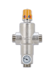
| Description | Referencia |
|---|---|
| Thermostatic mixing valve 1 1/4″ | 708TMZ114CAR |
| Thermostatic mixing valve 1 1/2″ | 708TMZ112CAR |
| Thermostatic mixing valve 2″ | 708TMZ200CAR |
3 Ways motorized valves
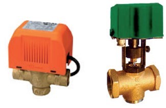
For primary circuits
| Description | Reference |
|---|---|
| 1/2’’ (Tmax 160 ºC) | 708ZN3V012H |
| 3/4’’ (Tmax 160 ºC) | 708ZN3V034H |
| 1’’ (Tmax 160 ºC) | 708ZN3V100H |
| 1 1/4’ (Tmax 150 ºC) | 708ZN3V114H |
| 1 1/2’’ (Tmax 150 ºC) | 708ZN3V112H |
| 2’’ (Tmax 150 ºC) | 708ZN3V200H |
Static balance valve
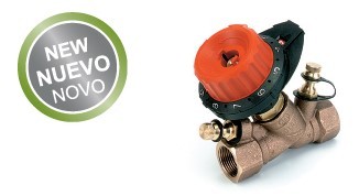
| Description | Reference |
|---|---|
| 1/2″H kv 0,1-4,47 m3/h DN15 | 708EQES012H |
| 3/4″H kv 0,13-5,9 m3/h DN20 | 703COWMZ015 |
| 1″H kv 0,17-8,52 m3/h DN25 | 708EQES100H |
Thermostatic mixer valve
| According to | UNI EN 1111 |
| Temperature range | 30-55ºC |
| Max. operating pressure | 10 bar |
| Max. inlet temperature | 100 ºC |
| Flow at a 3 bar | 38 l/min |
| Minimum flow | 10 l /min |
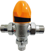
| Description | Reference |
|---|---|
| Body 1 « | 708TMZ100CT |
| Body 1″ with non-return fittings 3/4″ | 708MZ03CAT |
Solar Controllers

- 2 Temperature sensor inputs PT1000
- 1 Relay output 230VAC (on/off)
| Description | Ref. |
|---|---|
| Termicol 400S with 2 probes (1 relay 10A, sond PTC2000) | 703C7400S02 |
XTDC-V1
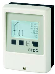
- Temperature sensor inputs PT1000
- 1 Relay output 230VAC (on/off)
- 1 PWM output (high efficiency pumps speed control)
- 9 Hydraulic options
| Description | Ref. |
|---|---|
| Termicol STDC with 2 probes | 703C1STDC32 |
XTDC-V1

- 8 Temperature sensor inputs PT1000
- 2 Grundfos VFS/RPS sensor input
- 1 inlet for RC21 environment sensor
- 2 PWM output (high efficiency pumps speed control)
- 2 Speed control connections
- 4 Relay output 230VAC (on/off)
- Micro SD Memory Card Slot
- Ethernet connection (model V2)
- 48 Hydraulic options
| Description | Ref. |
|---|---|
| Termicol XTDC with optional probe | 703C1XTDC10 |
LTDC-V3
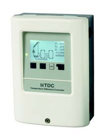
- 6 Temperature sensor inputs PT1000
- 2 VFS/RPS Directsensor inlets for flow measuring
- 2 Relay output 230VAC (on/off)
- 2 PWM output (high efficiency pumps speed control)
- 42 Hydraulic options
| Description | Ref. | P.V. P € |
|---|---|---|
| Termicol MTDC with 3 probes | 703C1MTDC53 | – |
MTDC-V5
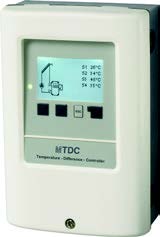
- 4 Temperature sensor inputs PT1000
- 2 Relay output 230VAC (on/off)
- 1 PWM output (high efficiency pumps speed control)
- 25 Hydraulic options
| Description | Ref. |
|---|---|
| Termicol LTDC with 4 probes | 703C1LTDC34 |
Filling and draining systems
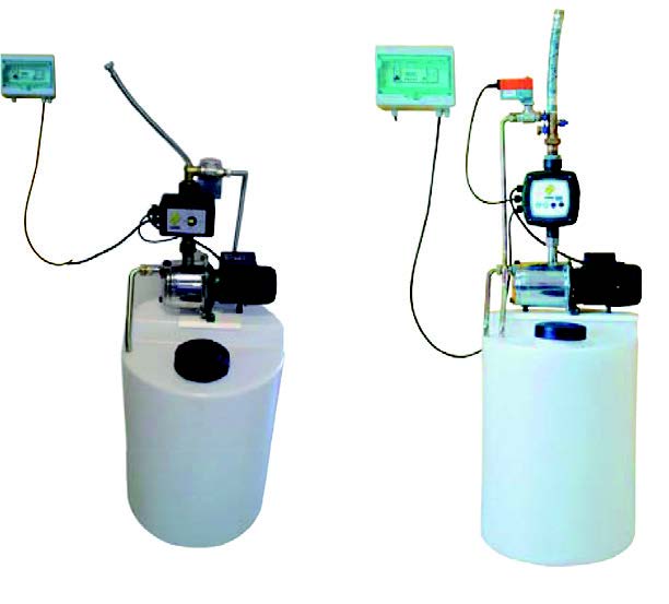
Digital equipment
| Nº Collector | Description | Reference |
|---|---|---|
| 6 – 15 | 120 l. | 712LLVD0120 |
| 16 – 25 | 200 l. | 712LLVD0200 |
| 26 – 35 | 300 l. | 706VAC300 |
| 36 – 50 | 500 l. | 706VAC500 |
| 51 – 120 | 1.000 l. | 706VAC0900 |
Electronic equipment
| Nº Collector | Description | Reference |
|---|---|---|
| 1 – 6 | 50 l. | 712LLVE0050 |
| 7 – 15 | 120 l. | 712LLVE0120 |
| 16 – 25 | 200 l. | 712LLVE0200 |
| 26 – 35 | 300 l. | 712LLVE0300 |
| 36 – 50 | 200 l. | 712LLVE0500 |
| 51 – 120 | 200 l. | 712LLVE1000 |
Filling systems
| Equipment | Description | Reference |
|---|---|---|
| Manual equipment | 50 l. | 712LLEM050 |
| 120 l. | 712LLEM120 | |
| 50 l. | 712LLE0050 | |
| Electronic equipment | 120 l. | 712LLE0120 |
| 200 l. | 712LLE0200 | |
| 300 l. | 712LLE0300 | |
| 500 l. | 712LLE0500 | |
| 1.000 l. | 712LLE1000 | |
| Digital equipment | 120 l. | 712LLD0120 |
| 200 l. | 712LLD0200 | |
| 300 l. | 712LLD0300 | |
| 500 l. | 712LLD0500 | |
| 1.000 l. | 712LLD1000 |
Heat transfer fluid
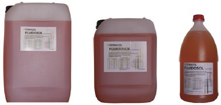
| Concentrated antifreeze “Fluidosol” | Reference |
|---|---|
| 2 l. | 707CGF0002 |
| 10 l. | 707CGF0010 |
| 25 l. | 707CGF0025 |
| 210 l. | 707CGF0210 |
| 1.000 l. | 707CGF1000 |
Expansion systems
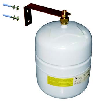
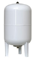
| Expansion vessel | Primary circuits | ACS / DHW / AQS | ||||||
|---|---|---|---|---|---|---|---|---|
| Solar | Heater | Intermediate | ||||||
| Ref. | P.V. P € | Ref. | P.V. P € | Ref. | P.V. P € | Ref. | P.V. P € | |
| 5 l. | — | 706VCR005 | – | 706VIN005 | – | – | ||
| 8 l. | 706SOL008 | – | 706VCR008 | – | 706VIN008 | – | 706VAC008 | – |
| 12 l. | 706SOL012 | – | 706VCR012 | – | 706VIN012 | – | 706VAC011 | – |
| 18 l. | 706SOL018 | – | 706VCR018 | – | 706VIN018 | – | 706VAC018 | – |
| 24 l. | 706SOL024 | – | 706VCR024 | – | 706VIN024 | – | 706VAC024 | – |
| 35 l. | 706SOL035 | – | 706VCR035 | – | 706VIN035 | 706VAC035 | – | |
| 50 l. | 706SOL050 | – | 706VCR050 | – | 706VIN050 | – | 706VAC050 | – |
| 80 l. | 706SOL080 | – | 706VCR080 | – | – | 706VAC080 | – | |
| 100 l. | 706SOL0100 | – | 706VCR100 | – | 706VIN100 | 706VAC100 | – | |
| 140 l. | — | 706VCR140 | – | – | 706VAC150 | – | ||
| 200 l. | 706SOL220 | – | 706VCR200 | – | 706VIN200 | 706VAC200 | – | |
| 250 l. | — | 706VCR250 | – | – | – | |||
| 300 l. | 706SOL350 | – | 706VCR300 | – | 706VIN300 | 706VAC350 | – | |
| 400 l. | — | 706VCR400 | – | – | – | |||
| 500 l. | 706SOL500 | – | 706VCR500 | – | – | 706VAC500 | – | |
| 600 l. | — | 706VCR600 | – | – | – | |||
| 700 l. | 706SOL700 | – | – | – | 706VAC700 | – | ||
| 800 l. | — | 706VCR800 | – | – | – | |||
| Connection kit | 704SETCGB | – | 704SETCGB | – | – | 704SETCGB | – | |
Probes
| Description | Reference |
|---|---|
| Contact temperature probe PT1000 | 703SDPT1000C |
| Temperature probe PT1000 | 703SDPT1000 |
Energy meters
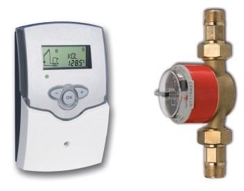
| Flow | Diameter | N. of probes | Reference |
|---|---|---|---|
| 0,6 m3/h | ¾ ” | 2 | 703COWMZ006 |
| 1,5 m3/h | ¾ ” | 2 | 703COWMZ015 |
| 2,5 m3/h | ¾ ” | 2 | 703COWMZ025 |
| 3,5 m3/h | 1” | 2 | 703COWMZ035 |
| 6,0 m3/h | 1” | 2 | 703COWMZ060 |
| 10,0 m3/h | 1 ½ ”” | 2 | 703COWMZ100 |
| 15,0 m3/h | 1 ½ ” | 2 | 703COWMZ150 |
Electric kits
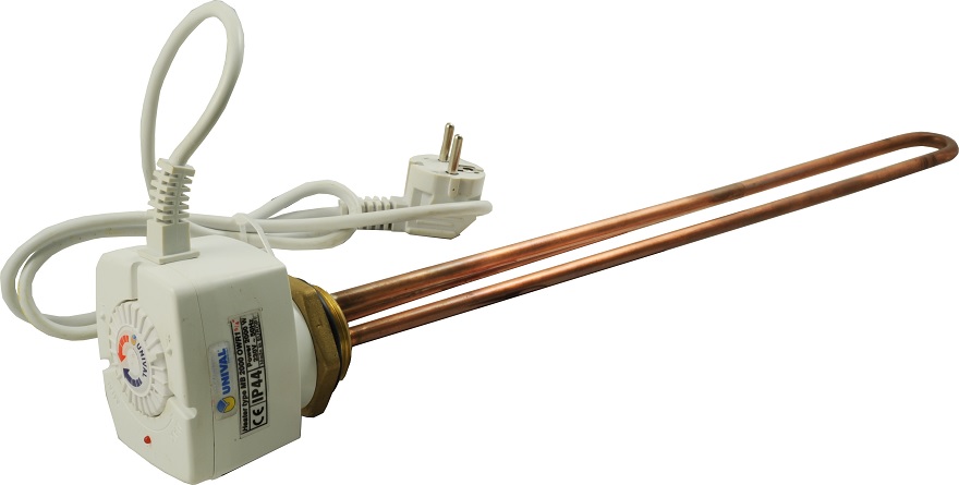
| Output | Voltage | Diameter | Reference |
|---|---|---|---|
| 2kW | Single-phase 230 V | 1 ¼ ” | 711KFK2000M |
| 3kW | Single-phase 230 V | 1 ¼ ” | 711KFK3000M |
| 4,5kW | Three-phase 400 V | 1 ½ ” | 711KFK4500T |
| 6kW | Three-phase 400 V | 1 ½ ” | 711KFK6000T |
| 9kW | Three-phase 400 V | 1 ½ ” | 711KFK9000T |
| 12kW | Three-phase 400 V | 2 ” | 711KFK12000T |
| 15kW | Three-phase 400 V | 2 ” | 711KFK15000MC |
| 18kW | Three-phase 400 V | 2 ” | 711KFK18000MC |


